OPLM Binding and Basic Telemetry
Summary
OPLink radios can be used in several different ways: for telemetry connection only, for telemetry + vehicle control, and for vehicle control only. The common thread for all these uses is binding, which also leads to basic telemetry data being transmitted over the link automatically.
This procedure will bind an OPLink mini to another OPLink, either to the integrated OPLink of the Revolution, or to another independent OPLink module. If you are binding two stand-alone OPLink modules together, it is recommended to first go through the OPLM CC - CC3D - Atom Hardware Setup page in order to prepare hardware for the binding operation. For Revolution, port setup or hardware changes are not necessary.
We will use the ground OPLink as a link coordinator, and the flight OPLink as a link slave. This enables full telemetry capabilities and makes it possible to use the link for vehicle control. If you are going to use OPLink for vehicle control, do this tutorial first, then proceed to the vehicle control tutorial. If you only intend to use telemetry, you can also make the flight OPLink the coordinator, but this does not have any additional benefits.
Antennas
Caution
From this point on, you should always have antennas connected to all OPLink modules. Neglecting this will cause permanent damage to the RF electronics.
Prerequisites
- Make sure that all modules are up to date by using the GCS Firmware Update & Erase feature, found in the Firmware tab. OPLink must be disconnected before clicking the update button. The OPLink that is integrated into Revolution will be updated when you update the flight controller firmware.
- If you are connecting a ground OPLink to another stand-alone module, set up the hardware first by following the OPLM CC - CC3D - Atom Hardware Setup page.
- To protect your hardware from short circuits, consider mounting the OPLink module inside a case or at least wrap it with heat shrink. DO NOT mount a bare board so that it can touch carbon fiber frame without insulating it first (carbon fiber is conductive).
- OpenPilot firmware can only support one Telemetry link at a certain time, so disable Telemetry going to OSD or Bluetooth module etc. DO NOT disable USBTelemetry.
- Check, and re-check that there is an antenna connected to both OPLink modules!
Binding
Coordinator side
- Connect to the OPLink module that you are going to use as Coordinator, usually the ground module.
- Go to the OPLink page in the GCS, available on the Configuration tab’s left bar. It is only visible if an OPLink or Revolution is connected.
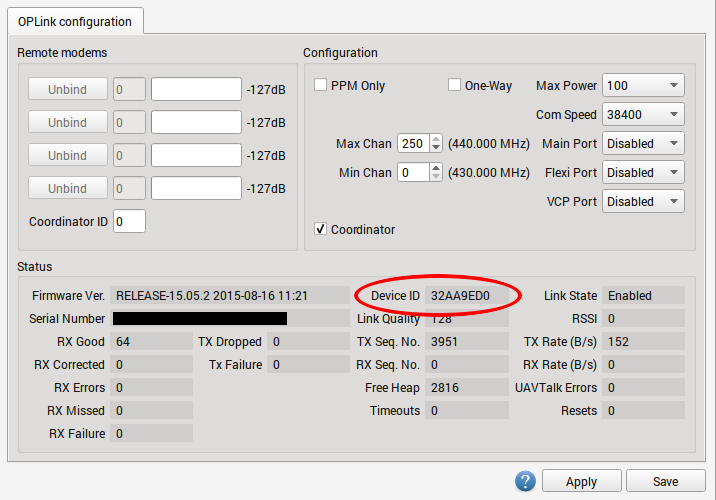
- Set the following recommended settings:
- “Max Power” 100 (or maximum for your country)
- “Com Speed” 38400
- “Max chan” 250
- “Min chan” 0
- Tick the Coordinator checkbox
- Click Save, wait a few seconds for the telemetry gadget (the meter at the bottom of the GCS) to calm down.
- Write down the Device ID. You are going to use it later.
- Disconnect from the coordinating module.
The OPLink Save button will display a green “tick” when settings are saved, but it can disappear soon after settings are saved. This is normal behavior.
Using custom frequencies
If your country allows only a fraction of the available frequency band to be used, you can adjust the operational OPLink channel range to reflect that. The GCS indicates minimum and maximum used frequency when you change min and max channels. Both OPLinks must have the same min and max channel pair to bind successfully.
Slave side
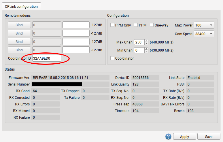
- Connect to the another OPLink device that is going to be the connection slave
- On the OPLink page in the GCS, set exactly the same Max Power, Com Speed, Max chan and Min chan as you did for the Coordinator. DO NOT tick the “Coordinator” checkbox.
- Enter the Device ID that you wrote down from Coordinator into the Coordinator ID text box.
- Click Save, wait a few seconds for the telemetry gadget (the meter at the bottom of the GCS) to calm down.
- Disconnect from the slave module. The bind is complete.
Testing the link for the first time
At this point, the OPLink modules have a successful bind and no more configuration steps are needed. The next step is to actually test and verify that the connection between the OPLink devices works properly. All OpenPilot devices should be powered off and disconnected from your PC before testing. This is because the modules need a proper power cycle to apply the changes we made, and because only one telemetry connection can be supported at a time. This means that if you have USB connected to the flight controller, only the USB connection gets telemetry, and the OPLink does not.
- Power on your vehicle using external power (i.e., a flight battery).
- Connect to the ground module with USB and observe GCS behavior as communication link comes online. The link usually takes between 10 and 30 seconds to establish, because there are a lot of settings objects that need to be downloaded through the link. You can observe the download process in System tab.
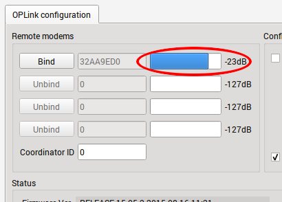
- Go to the OPLink Configuration page, and you should see a blue bar in the Remote modems area, which indicates signal strength.
Congratulations! Your OPLink telemetry connection is now ready for use. If you wish to use the connection for vehicle control also, proceed to the OPLM Vehicle Control Link page.
Advanced topics
Binding to multiple vehicles
You can use a single coordinator OPLink module to bind to multiple vehicles that act as signal slaves. They cannot be powered on simultaneously, but this allows you to get telemetry from many vehicles with just one ground module and no configuration changes. It even supports controlling multiple vehicles. This is established by repeating the slave side binding procedure for every additional OPLink.
Multiple Slaves
Caution
Use caution that only one vehicle at a time is powered with a flight battery, or you may have a second vehicle power up unexpectedly when you arm!
Using higher COM speed
OPLink supports higher COM speeds than 38400. If necessary, you can safely bump it up to 57600. After that, the range of the link decreases significantly. This makes it possible to transmit larger amounts of data and raise the update periods of various data objects (manually, in data object meta data). With faster data rate, ridiculous object update speeds can be achieved, but at the cost of range.
Using Bluetooth module with OPLink
It is possible to connect a Bluetooth module to OPLink, and establish a completely wireless telemetry link. In this setup, telemetry data is first transmitted between OPLink modules, and then from ground OPLink module to Bluetooth module, and finally a computer or a smartphone with integrated Bluetooth chip. Setup instructions can be found in the Bluetooth Setup for Telemetry page.
One way operation
If for some reason you want to only transmit with the other module, and receive with the other one, you can tick “One way” in both OPLink module settings. It will enable a special mode where only the coordinator module can transmit packets. The slave module receives packets normally.
Vehicle control link only
For those extra long or safety critical flights OPLink can be brought into a special mode where nothing but PPM vehicle control signal is transmitted from coordinator to slave. This enables a custom communication speed and protocol in OPLink. You can enable it by ticking “PPM Only” at both OPLink module configs. The control link has to be set up normally using OPLM Vehicle Control Link page instructions.